Unscrewing mold: Design Logic and Practical Engineering Solutions
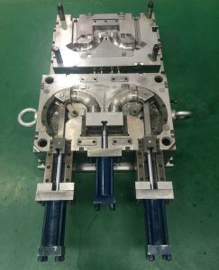
Unscrewing mold
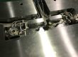
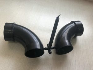
Unscrewing molds are essential for producing plastic parts with threads, such as bottle caps, pipe fittings, and precision nuts. Unlike standard core-pulling molds, unscrewing molds must rotate the core to “unscrew” it from the finished part, ensuring the integrity of the threads during the ejection process.
Unscrewing Mold
In engineering practice, the success of an unscrewing mold design lies in the synchronization of the rotation mechanism, transmission precision, and the stability of the demolding process.
1. When to Use an Unscrewing Mold?
Unscrewing molds are required when a part features internal or external threads that cannot be released simply by the opening motion of the mold.
Typical Applications:
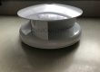
Bottle caps
Threaded pipe fittings
Precision threaded nuts
Plastic housings with lateral threads
If the incorrect demolding method is used, it can lead to:
Damaged or deformed threads
Difficult demolding
Accelerated mold wear
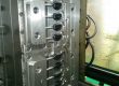
2. Design Logic of Unscrewing Molds
The core of the design is converting the opening motion of the injection molding machine into a precise rotational motion for the mold core.
Engineering Workflow: Part Geometry → Thread Features → Mold Opening Motion → Drive System (Gear/Rack/Motor) → Core Rotation → Smooth Thread Release
The goal is to ensure the rotation speed of the core perfectly matches the thread pitch, preventing any scratching or damage to the threads during demolding.
Unscrewing Mold
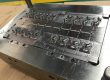
3. Unscrewing Mechanisms and Drive Systems
Depending on production requirements, thread depth, and space constraints, the following drive systems are commonly used:
3.1 Rack and Pinion Drive
Principle: Uses the mold opening motion to drive a rack, which rotates a pinion, subsequently rotating the core.
Advantages: Compact structure, excellent synchronization, suitable for small-to-medium molds.
Best for: Standard threads in space-constrained molds.
3.2 Hydraulic Motor Drive
Principle: Uses a hydraulic motor to drive the core rotation via a chain or gear set.
Advantages: High torque, adjustable speed.
Best for: Large molds and complex threads that require high torque.
3.3 Electric Motor/Servo Drive
Principle: Uses a servo motor for precise control.
Advantages: Superior rotational speed, high positioning accuracy, and the ability to execute complex demolding sequences.
Best for: High-precision medical products, electronic components, and parts with strict cosmetic requirements.
4. Key Design Parameters
Pitch Matching: The rotation travel of the core must correspond exactly to the thread pitch and number of turns. Mismatching will result in crossed or damaged threads.
Gear Ratio: The gear ratio must be calculated based on the specific thread characteristics of the part.
Rotation Timing: The rotation must be perfectly synchronized with the mold opening. Premature or delayed rotation can cause part deformation.
Sealing and Support: Rotating cores require high-quality bearings and seals to prevent plastic leakage and excessive wear.
5. Common Problems and Solutions
Thread Marring: Usually caused by poor synchronization or high surface roughness on the core. Solution: Improve core polishing and check for clearance in the transmission mechanism.
High Demolding Resistance: Often caused by the part shrinking too tightly onto the core. Solution: Optimize the cooling system and increase the core draft angle where appropriate.
Core Wear: Long-term use causes wear on components. Solution: Use wear-resistant materials for critical transmission parts and design modular, replaceable thread inserts.
Conclusion
Unscrewing molds are a critical component of precision injection molding. Successful design relies on precise calculation of the transmission system, strict control of motion timing, and optimization based on material characteristics. As a professional mold manufacturing company based in Shanghai, we possess extensive experience in developing high-performance unscrewing molds, ensuring defect-free production for your precision threaded components.
Unscrewing Mold