Technical Principles of Injection Mold Design: Structural and Kinematic Excellence
Precision in injection molding is rooted in the mechanical integrity of the mold design. Our engineering approach treats the mold as a high-performance machine tool, focusing on thermal equilibrium, mechanical synchronization, and steel-safe geometry.
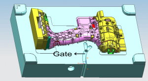
1. Manifold Engineering and Feed System Rheology
The design of the runner system and gate placement is critical to ensuring balanced cavity filling and minimizing molecular orientation stress.
Rheological Balancing: For multi-cavity tools, we utilize Geometrically Balanced Runners to ensure identical pressure drops and melt temperatures across all cavities.
Gate Geometry: Based on the polymer’s shear sensitivity, we specify Tapered Sub-gates or Valve Gates to achieve optimal packing without inducing gate freeze-off prematurely.
Cold Slug Well Design: Every runner system must include cold slug wells at each turn to prevent un-melted pellets from compromising the part’s mechanical properties.
2. Kinematic Systems: Sliders, Lifters, and Ejection
Complex part geometries require synchronized mechanical movements to facilitate defect-free demolding.
Slider Mechanics: We utilize Angle Pins (Horn Pins) or hydraulic cylinders for undercuts, ensuring a minimum clearance of 0.05mm at the sliding interface to prevent galling.
Ejection Balance: Ejector pins are positioned based on the part’s geometric center of friction. For thin-walled housings, we employ Blade Ejectors or Stripper Plates to prevent stress whitening or structural puncture during the ejection cycle.
Guidance Systems: All high-precision tools utilize DME/HASCO standard leader pins and bushings with integrated graphite lubrication for millions of cycles of kinematic repeatability.
3. Thermal Management and Cooling Circuit Optimization
A mold is essentially a heat exchanger. Design efficiency is measured by the uniformity of the cooling front.
Circuit Geometry: Cooling channels are designed with a minimum diameter of 8mm to 10mm, maintaining a distance of 2-2.5 times the diameter from the cavity surface for optimal heat transfer.
Baffles and Bubblers: For deep cores where standard drilling is impossible, we implement high-conductivity copper-beryllium inserts or bubbler systems to eliminate localized “hot spots.”
Conformal Cooling: For cycle-critical components, we utilize 3D-printed Maraging steel inserts with conformal cooling paths that follow the part’s contour, reducing Delta-T variance to <2°C.
4. Metallurgy and Component Hardness Validation
Steel selection is determined by the resin’s abrasiveness and the projected tool life (Class 101-104).
Core/Cavity Steel: We specify S136 (ESR) for optical or medical parts requiring corrosion resistance, and H13 (hardened to 50-52 HRC) for high-volume automotive components.
Wear Components: Sliders and wear plates are designed with dissimilar steels (e.g., P20 vs. 738H) to reduce the coefficient of friction and extend service intervals.
5. Case Study: Precision Mold Design for an Internal Gear
Project: Precision Actuator Gear (Material: POM/Acetal)
Technical Challenge: Maintaining a Total Composite Error (TCE) of <0.02mm while managing the high shrinkage rate (approx. 2.0%) of POM.
Engineering Execution:
Implemented a Symmetrical 4-Drop Hot Runner system to achieve center-gating, ensuring uniform radial shrinkage.
Utilized Precision-Ground Gear Inserts with a steel-safe allowance of 0.05mm for T1 fine-tuning.
Integrated a Two-Stage Ejection System to prevent distortion of the gear teeth during demolding.
Data Result:
Concentricity achieved: 0.015mm.
Tool Life Expectancy: 1,000,000 shots with zero significant wear on critical tooth profiles.
6. DFM Integration and Steel-Safe Strategy
Our design philosophy follows a “Steel-Safe” protocol, allowing for micro-adjustments post-T1 trial without the need for welding or major remachining.
Interchangeable Inserts: Critical wear areas or high-tolerance features are designed as separate inserts for easy maintenance and calibration.
Alignment Control: We use Side Locks and Top Locks to ensure precise core-to-cavity alignment, neutralizing the effect of thermal expansion on the molding machine’s tie-bars.
Engineering Audit Summary
Based in Shanghai, our design team bridges the gap between theoretical CAD models and floor-shop reality. Every Injection Mold Design undergoes a rigorous peer review of its kinematic timing and thermal cooling capacity before steel cutting begins. We deliver not just a tool, but a calibrated production system.